
Goal
Understand diffusion and its effects.
Diffusion
Ideal diffusion can be defined as “the energy density being uniform in the region considered and when all directions of energy flux at all parts of the region are equally probable.” – Acoustic Measurements - Beranek. Diffusion can get very complex but there is also a simpler side to things that can help guide our understanding without needing to delve into upper division mathematics and physics. That is what we will be focusing on.
The word diffusion comes from latin diffringere - to break into pieces.
An ideal diffuse field has several properties:
The frequency and spatial irregularities obtained from steady-state measurements must be negligible.
Beats in the decay characteristic must be negligible.
Decays must be perfectly exponentials (they will appear as straight lines on a log scale.)
Reverberation time will be the same at all positions in the room.
The character of the decay will be essentially the same for all frequencies.
The character of the decay will be independent of the directional characteristics of the measuring microphone.
These come from the Master Handbook of Acoustics Ch. 9
Ideally diffuse fields will sound the same anywhere in the field. No matter where you go the same sound properties will be present. Too much diffusion is bad because it will blur the “sonic space”, but to little is also bad as we will end up with possible flutter echo and nasty early reflections. In general, there are three stages to a room; the direct sound, the early reflections, and the late reflections. Many reverb plugins have controls that reflect this. The late reflections approximate a diffuse field because they have had more time to bounce around and distribute their energy. Hence when we talk about diffusion, we do so with a couple goals,
To talk about and manipulate the long-term sound field in a room.
To augment early reflection’s (though absorption is typically used for this)
To decimate room modes (standing waves)
The basic idea is that we will place constructs on the walls of a room so that any incident wave from any angle when hitting our diffuser will reflect equally in all directions. We have already seen some basic examples of diffusion, such as convex surfaces. It should come as no surprise then that for a diffuser to be effective it must be of a similar size or bigger to the wavelength of the frequency we wish to diffuse.
There are many types of diffuser technology, but we will only discuss a couple that are effective, well studied, and can even be easily made. You may be surprised to find that some objects in your space may already act as a diffuser such as a bookcase!

Diffusion Measurement
Measuring the diffusion of a room has several flavors and I will give a simplified definition here. The two principle ways are steady state measurements, and fixed measurements, others exist but these can be done easily with minimal gear. First you will need a measurement microphone that has been designed to be as accurate as possible. You may be surprised that some of these devices are not as expensive as you think.
Steady State
In steady state measurement you place a speaker in a position to account for as many modes as possible, usually in a corner and a microphone in a similar position. Then you use a sine-wave sweep, or a noise profile to record the spectrum. If any part of the graph averaged over time is uneven this is evidence of a lack of diffusion.
Fixed Measurements
In this method you move the highly directional measurement mic to various places in the room and record a response from a loudspeaker that is held constant. You do this for many frequency’s and average the results for the various places in the room for each frequency creating a “map” of the room giving you insight into how the diffusion profile of your room looks.
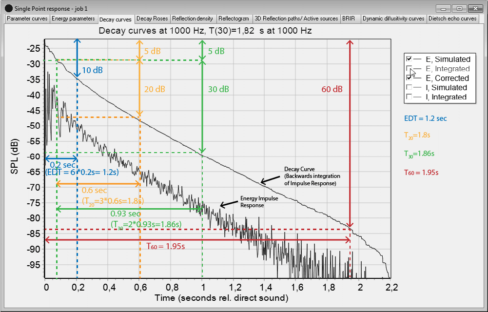
Exponential Decay
One of the requirements for diffusion is exponential decay. This is easy to test, simply set off a transient sound in the space and record it. If the decay is not exponential, then you have evidence of diffusion problems. Keep in mind that some frequencies will diffuse more than others for various reasons, it could be the shape of the room, the size of the frequency, or the coupling of one room to another. But it’s easy enough to get a graph of the decay and see what it looks like. Keep in mind that exponential decays will look linear on a logarithmic scale so using a log scale will make it easy to see.
Dirac Pulse
The ideal transient event would be a Dirac Pulse. Such a pulse can be approximated by popping a balloon. The dirac pulse has some special properties:
Contains all frequency
It is instant
Its magnitude is infinite
We cannot have such a signal in reality but we can get very close to it. A clap, gun shot or other short burst of sound can work. In general clapping is not a great way to emulate such a pulse but can work in a pinch. The digital version of such a spike is all 0's then a 1 and then the rest are zeros such as: ...,0,0,0,1,0,0,0,...
Such a spike has a special property for linear systems. Linear systems are systems in which results add and scale. So if our input is added or scaled we can determine the output. I don't want to go to far into this topic as it leads to the entire world of filter design but suffice it to say that the dirac pulse is a special signal, in a way it represents a single instance of an input. We can view all other inputs as such a bunch of dirac pulse chained together.
So we we know how the system responds to a dirac pulse we can determine how it will respond for any input! The response to such an impulse is known as an impulse response. Knowing this response, and knowing the system is linear (we approximate rooms as linear although this is not really the case it's often good enough), we can determine any output! In other words we can estimate how a sound will "sound" in a room after its bounced around in it!
This video gives a good visualization on the math behind impulses:
This process leads us to a math operation called convolution. We will talk more about convolution when we talk about reverb. For now I just want you to know why we care about these short loud sounds, they have special properties.
Transient and Sine-wave Sweep
Two primary methods for getting a room response exist. They are transient excitation and the sine wave sweep.
Having the room response or "impulse response" will allow us to understand our room and also recreate it if we so wish! Once we have a room response we have its reaction to a single impulse. So if we run our signal through the impulse responce via convlution we will get a result that is as if we played our sound in the room that impulse response came from! This is the principle behind convolution reverb, or convoluers in general. They are used in distortion, modeled emulations of analog gear, reverb, acoustics, and guitar amp and cab simulations. Convolution is a major part of digital signal processing. Its the act of how 2 signals "interact". We will leave it at that. What we need to know is that if we have an impulse response we can characterize that room, so we want that response!
The first method Transient Excitation is the simplest way to get an impulse response, just make an impulse! Then record what the system does. In our case the system is a room but a system could be a piece of gear or mechanical system as well, such as a car for example. In general we play a short burst of sound (ideally a dirac pulse, an instant 1 followed by 0’s) is played and the response from that sound is recorded. These recordings are called Impulse Responses. This must be played loud enough to excite the room / system.
The second way to get an impulse response is to play every frequency and see how it responds to each. A sweep of sine-wave frequency is sent into the room and recorded. We need to get rid of the sine wave sweep from the recording so we only have the "response", so a deconvolution filter is used to remove the sweep and we obtain the impulse response. This is how most acoustic measurement softwares such as room wizard eq work.
Exponential Decay
An exponential decay will have a straight line profile on a log scale. Any deviation is due to a room influence such as room modes, coupled spaces, and uneven acoustic treatment. Great deviations from a straight line profile indicate non-diffuse conditions.


Using Reverb as a Evaluation
If we measure the reverb profile at different points in a room we can tell if diffusion prevails. We can do this by looking at the reverb for different frequencies. We can take multiple measurements and then compare them at each frequency, if the reverb time differs a lot then we have evidence of non diffuse conditions.

Types of Diffusers
The two branches of diffusion technology we will get into are poly-cylindrical diffusers, and phase grating diffusion technology (Schroeder Diffusers).
Poly-cylindrical Diffusers
Poly-cylindrical diffusers are based on good ol geometry. They also have the added benefit of not only diffusing but also acting as low frequency absorbers! Poly-cylindrical diffusers have various shapes but they essentially are convex surfaces that when a sound ray hits the diffuser it is directed in a new spread out direction. This keeps the sound bouncing around in the room longer and spreads the sound out. There are some criticisms because the ray is still specular in nature. Its kind a like taking a picture and blowing it up so the resolution goes down on the image, however in acoustics this isn’t a totally fair comparison because waves diffused this way will hit different walls, objects, and surfaces which will alter the specular image greatly. Not to mention there may be multiple diffusers in the room! Phase grating technology is the answer to this criticism as we will see shortly but poly-cylindrical diffusers can sound very good make no mistake.
There are a couple things to keep in mind when using poly-cylindrical diffusers. The first is the size of the diffuser should be similar in size to 1/4th the lowest wavelength that you want to diffuse. You also in general don’t want to line these diffusers up as the entire point is to spread the sound out, but if you line them up you are at risk setting up a larger pattern for some frequencies as a result of the line of the diffusers. If you put many of these diffusers next to each other then consider varying their size by 10% or more to combat these problems. Finally, you can use many poly-cylindrical diffusers strategically to act as one large one, but this strategy is not usually an option for small rooms.
Here is a thread with great discussions and many papers referenced that cover many aspects of poly-cylindrical diffusers.
Phase Grating, Schroeder Diffusers
Manfred R. Schroeder in the 1970’s speculated that number theory could be used to create a diffuser that could be very effective. This was the indeed the case! However, some of the reasons behind why number theory works are complicated. There is also the fact that our understanding and methods have been improved on since the 70’s. For these reasons I will not make an effort to explain how the numbers came out to what they are, and we will instead take them on faith. Hyperlinks are provided to papers that details the sequences of numbers and why they are what they are.
Because Schroeder Diffusers are based on number theory they all have a “pattern” behind them despite their random looking appearances.


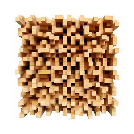
These patterns, as is typical, must be of similar size of the wavelength they are intended to affect. One disadvantage of these types of diffusers is they have band-limiting properties due to their construction. They are typically only effective over the range of somewhere between one half an octave to an octave. Despite this they still often outperform diffusers based primarily on geometry. Further, much research has happened since the 70’s and now there are all manner of diffusers, from the very thin yet effective, to metasurface diffusers, a very recent technology, and the classics such as the QRD, PRD, and Polys! These diffusers fall under the term phrase-grating. Phrase-grating diffusers have many pieces that are lower and higher that take a wavefront and separates the wave by different amounts depending on where it hits the diffuser, or in other words like a cheese grater doesn’t grate all the cheese but only that front part of the cheese block which is currently at the grater into tiny pieces, so too does a phase grater delay the phases of different parts of a wavefront causing it to split up. Diffraction also occurs helping the diffusion along.


How high and low to make each piece is defined by different series of numbers and methods depending on the type of phase-grater you are making. There are several types and we will talk about just a few.
Maximum Length Sequence Diffusers
Maximum Length Sequence Diffusers (MLS) the first type of diffuser purposed by Schroeder that kick started a new movement in acoustics. An MLS diffuser uses a series of vertical strips where the width of the strips is determined by the MLS used and is scaled by ½ the design frequency wavelength. The depth of the cavities should be ¼ the wavelength of the lowest frequency you plan to diffuse.

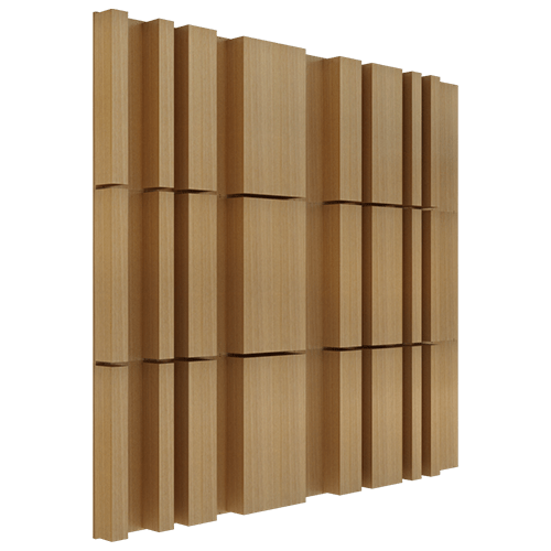
The depth of each well is denoted by a 1, and the 0 being no depth. By looking up an MLS sequence you can easily construct such a diffuser. MLS diffusers have a flat power spectrum across all frequencies. These however have a limited bandwidth (usually less than plus or minus ½ an octave). You will still find the type of diffuser used all over in the construction of buildings since it is an easy design to include.
The major MLS shortcomings are they have very limited bandwidth and the sequence itself may re-radiate waves in phase at some frequencies due to the sequence used. For example, the well depth being ¼ the wavelength while the width is ½ the wavelength will cause a ratio to be set up giving some in-phase results across the spectrum that lead to reflections off the diffuser are not ideally diffuse.
Diffuser Design
For N = 7 the sequence is: 0,0,1,0,1,1,1

Diffuser Design
Given that the MLS sequence for 15 is 1110101011010111011011, draw a 1 dimensional picture of what the diffuser would look like.
Given that the lowest frequency to be diffused is 1kHz, what should the width and depth be of each section?
Assume the design frequency is 200Hz, what are the design dimensions now?
Getting an MLS Sequence
We will no go into detail on how MLS sequences are generated, but here are some references.
Spread
A strip based diffuser (MLS, Poly’s, QRD etc … ) when positioned so that the strips are vertical will spread sound out in the horizontal direction. When positioned horizontally sound will be spread out in the vertical direction.
Quadratic Residue Diffusers (QRD)
An extension of MLS diffusers quadratic residue diffusers extends the range of the MLS diffusers and similarly are designed based on scaling the dimensions of the diffuser by the lowest frequency to be diffused.


Well Depth and Width
The max well depth should be determined by the lowest wavelength to be diffused. The well width should be half a wavelength of the shortest wavelength to be scattered. This sets the high frequency cutoff of the QRD. The well width has some nuance to it when considering off axis sound but we will go with this simple version for now.
QRD Design
The way the QRD works is off of prime numbers. Prime numbers don't have any divisors in common. For example 5 break down only to 5x1 and 7 breaks down to only 7x1. This property of primes means that no parts of the waves will overlap and reinforce each other unevenly. We want to leverage this in our design.
The idea is we pick a prime number to work with, say 5. Since 5 is prime nothing divides it evenly. So If we divide 5 by 4 it won't go in evenly. There is will never be another whole number result like how 6/3 = 2. What we are interested in is the remainder that is left. 5/4 gives a remainder of 1, meaning after trying to have 4 go into 5 it would go in once and we would have 1 left over. These residuals (or remainders) come from the prime number and so they will ensure the wave is randomly dispersed. We will change the hight of the wells to match these residuals and scale them up or down based on our design frequency target.
The process is as follows:
Pick the lowest frequency you want to diffuse.
n2mod(p), where n starts at 0 and increases and p is a prime number that is non-negative and picked in advanced to find how deep each well should be.
To evaluate a mod, you simply divide by the number in the mod and instead of taking the result you take the remainder.
Design Question
Say for example you pick 5 as the prime number.
Then the first n is 0 and 02mod(5) =0.
Next n=1 and 12mod(5) which gives 1mod(5), 1 doesn’t divide 5 so the remainder is 1.
Next 22mod(5)=4 , again 4 doesn’t divide 5 so its 0 remainder 4 hence 4 is the result.
Continuing we get 4,1 and 0.
Notice when written vertically the results are:
0
1
4
4
1
0
This repeating is due to the mod and will always occur, hence you can repeat the pattern after the halfway point in this case after (5+1)/2. The larger the prime number you pick the longer the sequence will be. It will always be the case that the first and last are 0 and we have our prime number - 1 wells. In this case 5-1 so 4 wells.
We will talk about what to do with this sequence in a bit, but first some practice!
For the prime number 7 what is the QRD depth proportionality pattern?
Designing with the sequence
Say the lowest frequency we want diffused is 500Hz which has a wavelength of 2.26 ft or 27 in.
The quarter wavelength of this is about 6.78 in. This will be our deepest well.
For the case of n=5 we the pattern was 0,1,4,4,1,0
0 correlates the the no height, while p-1, where p is the prime, is the max height. You could choose to view 0 as the "least amount of wood cut away" and the largest value we have, in this case 4, as the "most wood cut away". This would also produce a QRD.
So for our case the two 4’s would be 6.78in and the two 0’s would be nothing.
We can convert all factors in the sequence into percentages relative to the maximum. So 4 would be 100% and 0 would be 0%. This gives us a new sequence of 0/4, 1/4, 4/4, 4/4, 1/4, 0/4, which in decimal gives 0, .25, 1, 1, .25, 0.
So the height we need for the wells with a factor of 1 is: 6.78in x .25 = 1.69 inches. You could also use proportions to do this. the ratio of 4/1 is the ratio of a well depth of 4 to a well depth of 1. We know this must be the same as a well depth of "no wood removed" our 6.78 inches to some unknown value x. This gives 4/1=6.78/x which also yields x=1.69 inches.
Now we know the well depth for each factor and all we have left to do is to build it!
Typical Way
Less Typical Way
Some QRD's have slits between the wells so that the wells have something to hold them up, such as in the first build video. These slits should be made as thin as possible to minimize their effect. It's relative to the target they diffuse so having some thickness is not going to make a huge difference but "in theory" they are bad.
In practice the charts have already been worked out for many prime numbers:

QRD Design Question
Say we are using the prime number 7, and our lowest frequency diffused is 800Hz. What are the well heights?
References
Fractals
Fractals can be used to increase the bandwidth of the diffusers.


What prime number do I pick?
It depends. In general we want to avoid repetition. The different primes offer different theoretical band widths. Ideally we pick a large prime number that will cover the space we want diffused although it is common to see multiple smaller arrays of QRD's used. If smaller arrays are used then we should use different design frequencies by at least 10% to avoid problematic repetition. Rotating them can also help.
Array's
In some situations arrays are used to fill a room out. In this case multiple repeating patterns of QRD diffusers are sometimes employed. This topic is one in which there are several schools of thought and at this time I do not yet have a solid source for why to pick on over another but in general:
Avoid repetition, if the scale is very large this may not matter as much.
Rotate some of the diffusers.
Change the design frequency of the diffusers by at least 10%.
Invert some of the diffusers.
A note about Bandwidth
Diffusers are generally scatter an octave above and below their bandwidth (excluding MLS diffusers), since these ranges are close to the design targets. Note this varies with design.
For example, say the frequency is 2kHz. Then the next octave is up 4kHz and the octave down is 1kHz. This is a very rough estimate however and you can expect as the frequency changes more for this to hold less and less true. The well width will effect the upper limit as well and techniques such as fractals can also affect this.
Determining Bandwidth
A diffuser has a deepest well of 4 inches. What is its bandwidth?
Design Tools
Pseudo Random Noise (PRN) Diffusers
Pseudo Random Noise Sequences (White Noise) can also be used to generate well heights. Many tools provide a PRN option. Pseudo means it is like random noise but not quite. Usually because it can be generated with the exact same numbers every time so it is "pseudo" noise. Its like a really good fake or disguise.
The only difference when it comes to designing is instead of using prime numbers, we use random noise to produce the factors for the build.
Primitive Root Diffusers (PRD)
PRD's differ from QRD's in the way we obtain the proportionality factors. We again use prime numbers but this time we use something call the "least primitive root". We will just use the known sequences and move on, but here is the equation and a little info:
D=gnmod(p)
Where g=least primitive root of p
n=integer>0
p=prime number
D=depth proportionality fact (how much to scale by)
The least primitive root is defined such that G is a primitive root of p if successive powers of G mod(p) generate all integers from 1 to p-1. I know it sounds fancy and you can hunt around numerically for these but there are plenty of charts online you can easily look up as well.
You just pick a p, find its least primitive root and get the sequence D, or just use a chart. Once you have D you need only pick the frequency range you wish to effect and then scale your well depths by the sequence D that results.

Skyline Diffusers
Skyline diffusers can be QRD, PRN or PRD. The are called skyline because they look like a city skyline.

Build
Diffuser Placement
Before we even consider placing a diffuser on a wall, our first question is how far should the diffuser be? Is the wall the best spot to place it?
It should be far enough that the lowest frequency diffused has had the space to fully form. We can use the quarter wavelength rule for this.
Question
Given the a diffuser that can diffuse down to 300Hz, how far from the speakers should it be placed as a minimum?
Binary Amplitude Diffsorber (BAD) (Active Absorber)
A flat surface with hole drilled into it. Uses Amplitude Grating instead of phase grating. Absorbs at low frequencies diffuses at high frequencies. Can be covered by fabric.
Design
Use a 2D pseudorandom binary sequence for best results. Avoids lobing. This is because this sequence will have a flat power spectrum. MLS sequences for example will work.
Build

Measuring Diffusion
To measure how effective a diffuser is we measure the sound intensity of the specular reflection and the sound intensity of the of that reflection at 45°. A coefficient of 1 is a “perfect diffuser”. This coefficient will vary with frequency.

Here is a comparison of the different diffusers and how they reflect on axis and off axis sound. We want this chart to be as random as possible, any pattern reveals a specular aspect to the diffuser.


Walls as Diffusers

Diffuser Effects
Makes things sound farther away.
Applied correctly can add definition to a sound.
Applied to much can remove definition from a sound.
Placing Diffusers in Rooms
It depends on the desired sonic characteristic you want for your room. A recording space will be treated differently than a control room or critical listening room. It all depends on where your sound sources will be and your intentions for that space!
Often in control rooms especially ones that aren’t very deep we place diffusion on the rear wall. Front wall is also a good location.
It is debated often about weather diffusers should be placed at points of early reflections. To really know what kind of solution is best the room should be measured. In cases with only mild early reflections diffusion may provide a better sound field. In cases with significant early reflections absorption at such points is a more appropriate treatment. Smaller rooms typically need more aggressive absorption treatment and less diffusion.
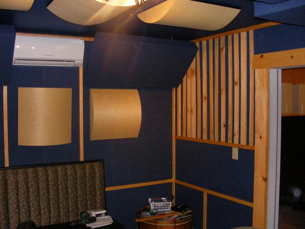
Room Examples
Here are some acoustic companies with rooms you can take a look at:
To support this series please consider donating via
paypalor joining the
patreon.