
Goal
Understand what acoustic absorption is and how to apply to a room.
Absorption
Absorption is the act of converting one form to another form which can then be used for another purpose. In acoustics we use this process to absorb problematic frequencies and then convert it to heat energy effectively removing it from the acoustic system. It’s like taking the trash out of your house but for sound!

Above we see many absorber types and their various general ranges of effect over the spectrum. In each case a wavefront hits the absorber, upon entering the absorber the wave bounces around inside it. The probability of this wave exiting the absorber determines how good at absorbing the absorber is. With each bounce the wave converts to another form of energy and the absorber does its job. Some absorbers allow a target of a specific frequency range, while other offer a more general effect.
Sound Wave Process
When a sound wave travels through the air some of its energy is lost to the air, this affects high frequency the most noticeably. The wave then hits an obstacle, some of the sound reflection and repeats the process, some of the sound may refract due to air temp changes, some may transmit and some is turned into heat due to friction based on the obstacle.

The Ideal Absorber
The ideal absorber is one in which sound enters and never comes back. Such absorbers exist! They are windows, doors, and other openings in which the sound freely passes through and doesn’t come back because it just keeps propagating. Naturally these absorbers invite a lot of other problems, so we turn our attention to other options. (We could also call this 100% transmission, it’s a matter of perspective.)
This video demonstrates it with light but the same principles can work with acoustics.
General Principles
In our conversation about reflections we learned how to find early reflection frequencies and where they occur. These locations should be the place we put the absorbers, but what kind of absorber do we use? How thick should they be? What should they be made out of?
There are a couple general principles that can lead us to some answers.
The lowest frequency an absorber can effect is determined by the thickness and density of the absorber. There are some special geometric cases to consider to.
The absorption coefficient determines how effective a material is at absorbing sound.
Changes in thickness and density throughout an absorber (nonuniformity) changes the effectiveness of an absorber.
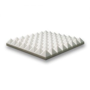
I want to address #3 right off the bat. Some Acoustic foam panels have a shape to them as if they would be diffusers:

This is done for two reasons. First, they look cool. This is a great reason to buy one absorber over another given they have the same performance. Second, it is often claimed the absorber also helps with diffusion. In most cases this is simply untrue in a meaningful way.
When foam constructs get large the shape can have an effect and is used in anechoic chambers along with some other considerations, including the fact that its often not just foam used and special coatings are used, but for most cases in studios it simply would be better to have a uniform brick of foam then a shaped one. There are a couple reasons for that.
Absorbers are designed to absorb and not reflect frequencies. If the sound just transmits through or reflects off the absorber because it’s in a range the absorber doesn’t absorb then it may as well just not be there. Some company’s even go so far as to say they shape their foam that way in order to help reflections! Well that’s not much of an absorber is it? Various factors can affect how deep a wave can penetrate various substances that we will talk about in a bit.
The size of the absorber determines the frequencies it can absorb, and since the material is already poor at reflection the fact that the shape causes some parts of the absorber to be thinner than other parts magnifies the fact that the absorber isn’t big enough to absorb the frequency so why would that mean the absorber can reflect it if that is also based on size?
So, don’t buy into the shape of absorbers. You will see people put up hilariously thin absorbers that are in fact made less effective by these patterns. The only reason you should buy absorbers like that is you like the look, or the performance difference is not enough to really matter.
For whatever reason in acoustics there are tons, and I mean tons of products that get purchased that have been their acoustic properties worsened on purpose because people like the shape. There are also products that can do a great job and are worth the money, and often you can build some pretty great absorbers yourself for really cheap. It comes down to understanding how an absorber works. It’s often easier to just buy multiple thinner pieces and put them together with spray adhesive if you’re on a really tight budget, or just build your own which is cheaper than you might think.
Absorption Coefficients
You may have heard of an absorption coefficient. It's a measure of how much sound a particular material absorbs. These are often measured and easy to find, but why not a coefficient of reflection?
In acoustics it often makes more sense to talk about absorption than reflection. It is easy to find absorption coefficients, less so for diffusion. This is because transmission, specular reflection and diffuse reflection can be difficult to isolate. Hence why we have absorptions coefficients for everything. It's typically a lot more practical.
Each material will have a different range of frequencies that it can absorb. It’s effectiveness at absorbing that range is called its absorption coefficient designated by α (alpha) as the most common variable of choice. This is a number between 0 and 1 that describes the percentage of the incident wave is absorbed. If we have an area of material for absorption called S, and we know is absorption coefficient α then:
A=Sα
Where A = absorption units (usually sabins).
If you have more than 1 material, simply do the equation multiple times and sum the results. There are various methods to measure absorption, the unit being named Sabin after the man himself for his pioneering work in measuring absorption, and they follow typical ideas about measuring. The ideas we will talk about are transient vs steady state vs a very specifically filtered result. These translate to Reverberation Tone Burst measurements, reverberation chamber measurements, and impedance tube measurements (Kundt tube). Each one has a way of generating an α. We will usually go on published charts, but here is a little info on these methods.
Reverberation Chamber
Get a chamber with a very long reverb time, the longer the better.
Blast it with sound and get the reverb time.
Place the absorption material in it, typically a set amount in the same configuration.
Using the new reverb time you can find the absorption attributed to 1 ft2 of the material.
There are many other details but this is the general idea.
Kundt Tube
A sample of the material is cut to fit tightly inside a tube.
A loudspeaker on the other end of the tube excites the tube to form standing waves.
Then by moving a probe we can determine the absorption coefficient using:
Note: Only accurate for normal incidence.

Tone-Burst Method
A short pulse of sound can be used. Proposed to deal with environmental noises.
Reflections take time to reach the measurement mic. The strength of the pulses can be used to find its absorption.

Warning about measurement methods on YouTube
A word of warning, there are many YouTube videos that show completely invalid ways of measuring α. For example in this one he has the mic on the other side of the absorber, so what he is actually measuring is transmission loss not absorption. It is an easy mistake to make. If this is how you measure absorption why not just get some highly reflective material and put it there, such as a brick? Most of it would be reflected and you would wind up with the false idea that this reflective material is somehow an absorber!
Here is a site that shows many absorption coefficients for various substances: Reference Link
It is typical of charts to give results at 63, 125, 250, 500, 1K, 2K, 4K and 8K Hz.
Looking at this chart you will see some coefficients greater than 1! How can this be? It is because of edge diffraction causing a higher value than 1.
Basic Design Principles
In order to meaningfully affect a target frequency, the absorber needs to be big enough, and as a general rule at least ¼ the wavelength of the lowest target in length, width and height.
In reflections we talked about where to place such absorbers and here we give a brief review and some additional insight:
Early reflections should be the target for the listening position, of which you can use a mirror to locate. Design the absorber to be large enough to affect the problem frequency.
Absorbers should be places with gaps between them for maximum absorption because of diffraction.
Diffusors placed should be done in such a way as to not introduce new early reflections to the listening position. (Only really a problem if your diffusor has severe lobing)
Absorbers should be placed to create a desired sound field target, usually a flat profile. Be conscious of how much you’re changing the spectrum of your room.
Stack knowingly. Placing air gaps between layers of absorption can increase of effectiveness of absorbers. This is why false ceilings, false floors and other design gaps are used.
Placing an absorber reduces the ambient sound field in general as you add absorption to a room. In this way absorption can be seen as general ambient noise reduction. To much can make a room sound "dead".
The Sabine
Named after Wallace Sabine.
Since a window is a perfect absorber an open window has an absorption coefficient of 1 and by definition a 1 ft2 window provides 1 sabin of sound absorption. Metric Sabines use a 1m2 window and 1 metric sabine = 10.76 ft sabines.
The First Absorption Equation
The sound absorption A provided by a particular area of material is obtained by multiplying its absorption coefficient by the surface area of the material exposed to sound.
A=Sα
Where A = absorption units (usually sabins).
S=surface area (sq ft, or sq m)
α= absorption coefficient
Question
A room as 20 ft2 of carpet. The carpet has an absorption coefficient of .55. What is the total amount of absorption in sabines?
Calculating an Entire Room
All materials in the room need their surface area measured and their absorption coefficient. Then you simple add them all up.
Since frequency varies with the absorber typically standard frequency are used to generate a rough spectrogram of its effectiveness. Often: 125, 250, 500, 1k, 2k, 4k
Question
What is the total amount of absorption in Sabines for a room that has a length of 30ft, a width of 20ft, and a height of 10ft. The floor is made of latex carpet, the ceiling is made of plaster, the walls are made of concrete. Use the following table:
| Type of Material | 125 Hz | 250 Hz | 500 Hz | 1000 Hz | 2000 Hz | 4000 Hz |
|---|---|---|---|---|---|---|
| Brick | .03 | .03 | .03 | .04 | .05 | .07 |
| Carpet (Heavy, on concrete) | .02 | .06 | .14 | .37 | .60 | .65 |
| Carpet (Latex, on foam rubber) | .03 | .04 | .11 | .17 | .24 | .35 |
| Concrete | .01 | .01 | .015 | .02 | .02 | .02 |
| Wood | .15 | .11 | .10 | .07 | .06 | .07 |
| Glass (Large heavy plate) | .18 | .06 | .04 | .03 | .02 | .02 |
| Glass (Ordinary Window) | .35 | .25 | .18 | .12 | .07 | .04 |
| Gypsum Board ("Drywall") | .013 | .015 | .02 | .03 | .04 | .05 |
| Plywood | .28 | .22 | .17 | .09 | .10 | .11 |
| Audience (On upholstered seats) | .08 | .27 | .39 | .34 | .48 | .63 |
| Concrete Block | .36 | .44 | .31 | .29 | .39 | .25 |
| Light Velour (Fabric on wall) | .29 | .10 | .05 | .04 | .07 | .09 |
| Plaster | .44 | .54 | .60 | .62 | .58 | .50 |
| Wooden Pews | .57 | .61 | .75 | .86 | .91 | .86 |
| Chairs (Unoccupied seats) | .15 | .19 | .22 | .39 | .38 | .30 |
Question
The lowest frequency is 1kHz. How thick should the absorber be at minimum?
Say we want to absorb 100 Hz. What thickness would we need?
Types of Absorbers
There are several types of absorbers.
Porous
Panel
Volume
Resonance
Porous are better at high frequency absorption, panel and volume/resonance absorbers do well at the low end. Though there are exceptions of course.
Porous Absorbers
Materials that have a bunch of “tiny holes”.
Carpet
Foam
Textiles
Fleece
Mineral wool
Acoustic Plaster
etc...
When a sound wave strikes a porous absorber the sound energy causes the fibers of that material to vibrate. This vibration will always be weaker than the amplitude of the wave. This motion causes the sound energy to transfer to heat energy. Cotton for example does well at this. Closed materials such as polystyrene, do not do well. This means not all thermal insulation will be good acoustic insulation. Typically due to the inability for the sound wave to go very far into the material.
Porosity
If fibers are to loosely packed little energy will translate to heat.
If fibers are to tightly packed sound penetration will become a problem.
Porous concrete can actually work as an absorber, but if it's spray painted it can lose its effectiveness. For this reason products such as “acoustic tile” exist, who have been made in such a way to keep the porous attribute intact. Cellulose or mineral fiber are good materials, of course you will want to check the specs of whatever solution you decide on.
The number 1 mistake people make is the size mistake. They buy to thin and to small. Remember you want it T H I C C. Foam is often seen directly and so it tends to be what comes to mind but other materials that are loose and are meant to be packed into a container to form an acoustic panel can also be great.
You will see an R scale as you look up some of these materials. This scale is a measurement of its resistance to heat traveling through it. It does relate to the thickness of materials, but it is better to get the α measurements than go off of the R scale. However, it can be helpful in getting the right dimensions.
When placing these absorbers, the points given before hold, but the layering option in particular works well with these. If you can create a gap between them and the mounting location this can increase the effectiveness of the absorber.

Sound carpet and curtains work on this principle. They can be very good at on site reflection reduction.
However, porous absorbers do little to nothing to low frequencies, especially low frequency standing waves.
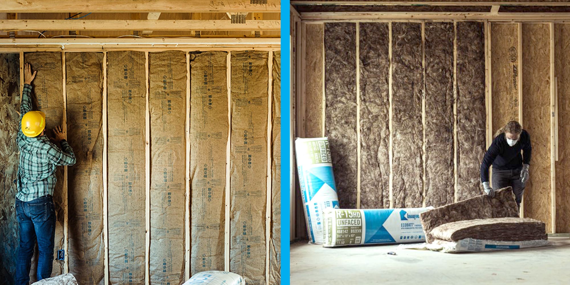
Glass Fiber Insulation
First, this can be dangerous to work with, take proper safety precautions when working with fiber glass.
The density is typically 1 lb/ft3, usually R-11 or R19. The backing paper on insulation can matter if mounted on walls.
Thickness:
R-8 = 2.5 in
R-11 = 3.5 in
R-19 = 6 in

Acoustic Tile
Common for drop in ceilings. The tiles themselves act as porous absorbers but the air above it cause them also to act as panel absorbers.


Question
Absorption is greatest when placed at what distance?
Are absorbers are most effect when placed directly on the wall? Explain your answer.
Mounting Variables
We can change the density, thickness, and the spacing it is mounted off the wall.
Changing Density

Changing Thickness

Changing Spacing Off Wall

Note that simply spacing the 1’’ absorber caused it to become similar to an absorber of 2’’ thickness in terms of absorption coefficient. So you can choose to mount off the wall, or stack absorbers. If you have the budget why not both?
Open-Cell Foam
Very common in many many applications, cars, planes, studios, offices, …
Worse acoustical performance compared to fiberglass.
Density is different (though this is not that important here)
Average thickness is much less (main issue)
Foam often costs more! Wrap your head around that.


Here is a comparison of that foam vs glass-fiber.


Not only does it outperform, it is far cheaper and can by done DIY style within a very reasonable budget.
Drapes and Curtains
Porous type - air flows through it. Things that matter:
Material Type
weight
How many folds, More folds = more absorption
Distance from wall, The ideal distance is again ¼ the wavelength for the same reasons as before.
Heavy typically means more absorption

Different Weight Velour

Different Spacing from wall

Question
What is the worst distance you can put the drap (or absorber in general) from the wall for the design frequency? Say we choose 500 Hz. What is this distance?
Carpet
Good at mid and high frequency absorption (unless you have some crazy thick carpet, some carpets have very thick underlay). Carpet absorption can be a major problem for some room designs because it reduces the effect the walls and ceiling will have if it is to absorptive for the upper side of the spectrum. It also does very little to the low end typically so low room modes will still be issues. This makes working with permanent carpet an important early decision.
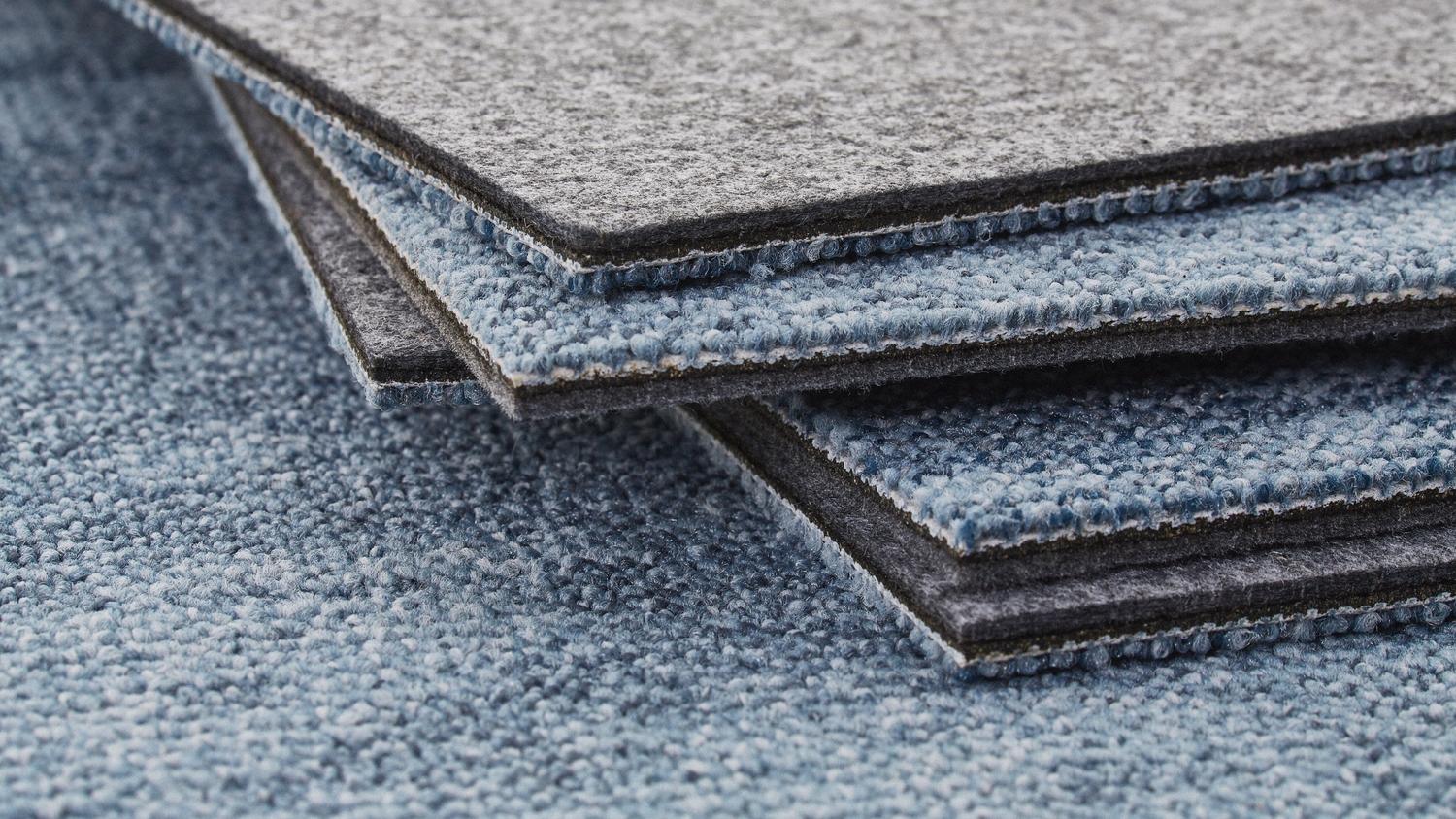
3 Carpets Compared

Underlay Compared

People Absorbers
Concert Halls that are full vs half full vs empty can have different acoustics. This issue exists of course for any room, concert halls are the go to example.
Consider your control room. Have clients listening? There more people in your room the more the acoustics can change.
2 Ways to combat this change: Have a freaking gigantic room, or design absorbers that can be used as “stand in people” so to speak.
Sound going past rows of people is greatly affected by angle. Lower angles is greater absorption.
| Situation | 125 Hz | 250 Hz | 500 Hz | 1000 Hz | 2000 Hz | 4000 Hz |
|---|---|---|---|---|---|---|
| College students informally dressed seated in tablet arm chairs | NA | 2.5 | 2.9 | 5.0 | 5.2 | 5.0 |
| Audience seated, depending on spacing and upholstery of seats | 2.5-4.0 | 3.5-5.5 | 4.0-5.5 | 4.5-6.5 | 5.0-7.0 | 4.5-7.0 |
The Air Itself
In very large spaces the air can become is significant absorber for 2kHz and higher.
Aair=mV
Where m = air attenuation coefficient, sabins/ft3 or sabins/m3, V = volume of room, ft3 or m3. m varies with humidity.
Bass Trap (Resonance Absorbers)
Bass trap is a pretty loose terms that can include panel absorbers and reactive cavity absorbers. This is a box or cavity of a critical depth with a mouth opening of a size to suit particular purposes. They are tuned to a quarter wavelength of the design frequency.

Things to note
Sound pressure at the opening is at max.
This implies the air particle velocity is zero at the opening. (The particles are "bunched up" and ready to push apart.)
At the closed end sound pressure is zero.
Therefore particle velocity is at a max at the closed end.
This is for an open pipe, if we consider placing a panel there that can resonate the panel will force a 0 pressure point at the panel. Thus:
The panel has maximum particle velocity and so resonates, the energy used to move the panel is why it acts like an absorber.
Since the panel is designed to be a quarter wavelength the particles will have max pressure (max kinetic potential energy) at the back of the panel.
Placing absorbent material at this location will make the trap even more effective.

Helmholtz (Volume) Resonator
First - Helmholtz was a studd. He wrote a book which can be had for free! The man was a genius in several fields, acoustics was one of many and this is but a small subsection of what he did.
Used for low end absorption. The air in the cavity is the spring, the air in the neck acts like a “mass” on a spring, vibrating at the natural resonance of the system, much like how a weight attached to a spring will. Absorption is max at the resonant frequency, and decreases quickly as you move away from it.
Square Opening Equation
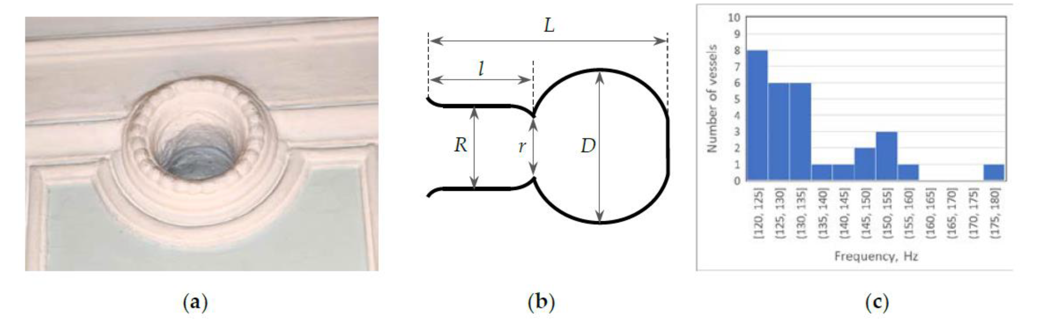
Circular Opening Equation
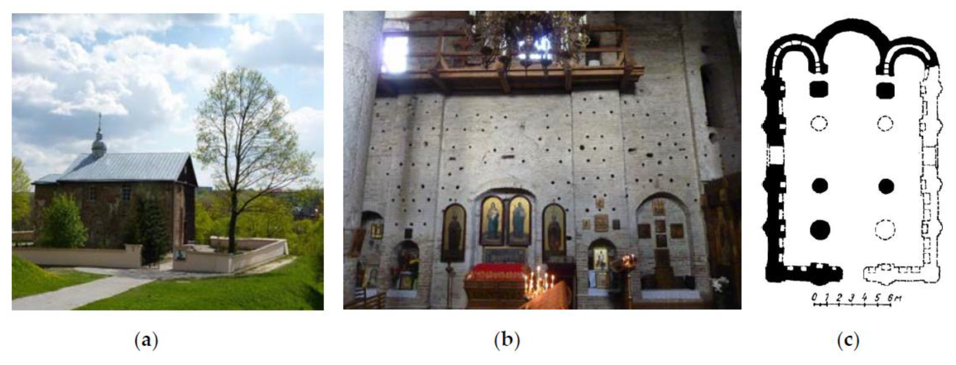
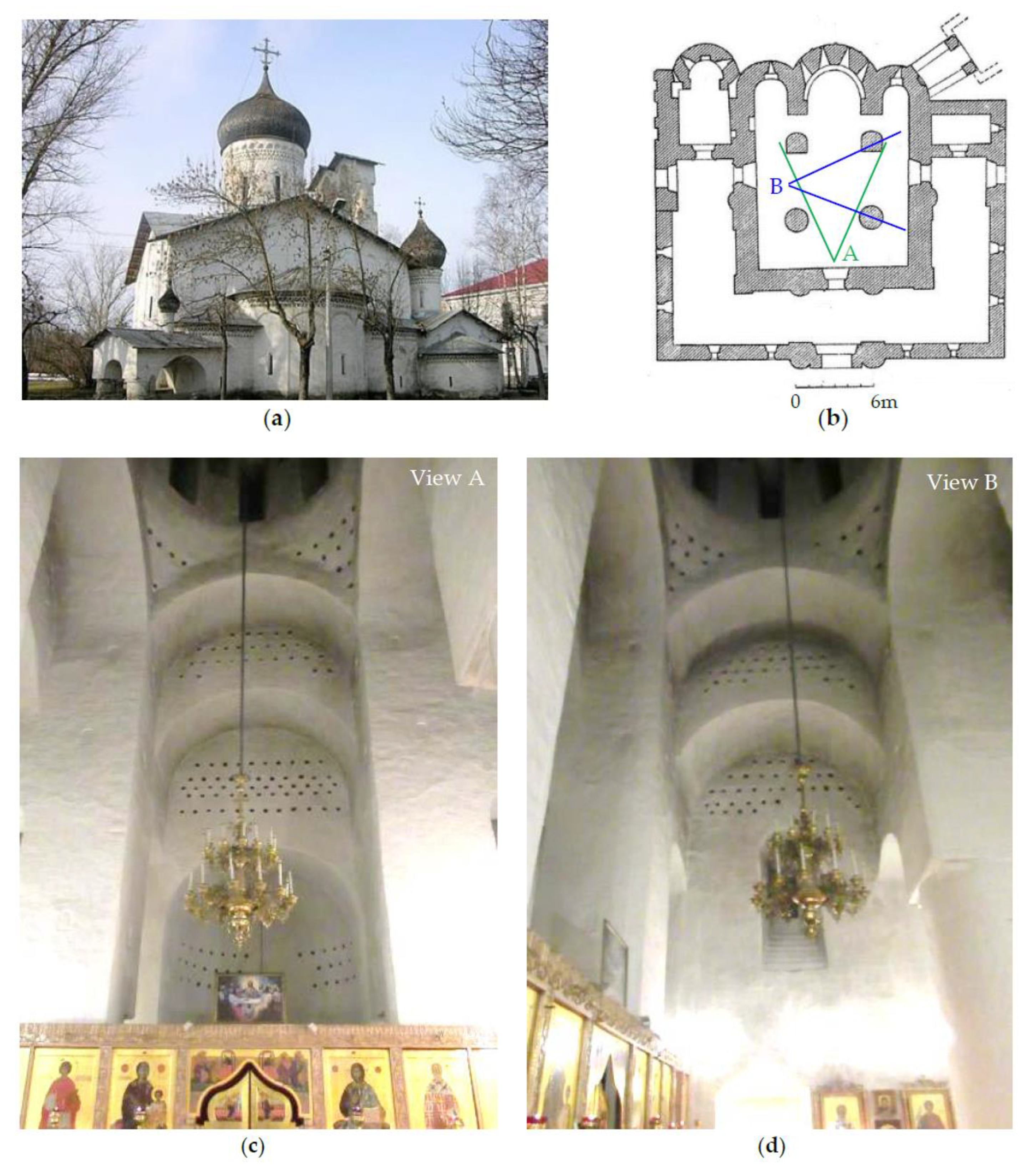
To get the max absorption the absorber should be placed in a place of high modal sound pressure of the design frequency. These frequency bands can be extremely narrow with an incredibly high Q value. Sound not absorbed is reradiated from the resonator opening! Typically in a hemispherical pattern, thus diffusion is also obtained. Helmholtz was not the first to use this technology by a long shot, there are jars in open theaters, churches and more, small and large for different ranges of frequency.
Helmholtz resonators have a very narrow band of frequencies they absorb. It acts as a bandpass absorber.

The Q factor of this system can be used to increase or decrease reverb. This is because helmholtz absorbers can also ring since it is a resonant system. This adds to reverb time to a room. It is related to the Q factor which can be found as the center frequency divided by the bandwidth of the two 3dB frequencies. (This system is a band pass system.)
A higher Q gives a longer reverb, and a lower Q gives a shorter reverb. Such designs to lengthen or shorten reverb time can be done by tuning the cavities and picking the proper material to use.
| Q | Reverberation Time (sec) |
|---|---|
| 100 | 2.2 |
| 5 | .11 |
| 1 | .022 |
Here is a before and after of such a room:
Before

After


They can be filled will absorbent to broaden its bandwidth.

Cinder block and other types of material can be combined to form a slot-type resonator.


Design
We wish to design a helmholtz resonator with a circular opening. We desire to absorb 125Hz. We want the length of the resonator neck to be 6 inches. What volume is required?
We wish to design a helmholtz resonator with a circular opening. We desire to absorb 175Hz. The volume is to be 10 cubic feet. What is the required neck length? After finding the required length determine if such a design is reasonable.
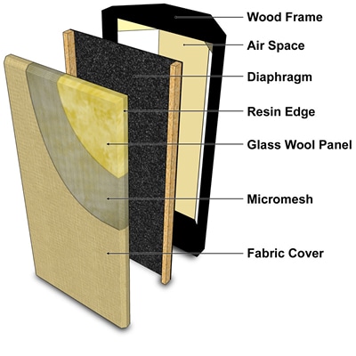
Panel (Diaphragmatic) Absorbers
A mass suspended from a spring will vibrate at its natural frequency when excited by an event. This same behavior happens with a properly designed panel with an air cavity. Think of blowing over a bottle lid, only in our case the cavity is sealed. Sound gets absorbed through the panel motion due to friction, just like how an excited spring eventually stops due to friction. Panel absorbers can also radiate some energy back, so limp materials that suffer more from friction will perform better.

As the panels velocity increases, which is max at its resonant frequency) so will its ability to damp that particular frequency. More air space behind the panel creates a less stiff spring, and less air space makes a stiffer spring. Given a flat unperforated panel we can use this for an approximation of the resonant frequency:
We can use the following depth vs surface density chart in order to design a panel:

Design
Design can work well with plywood, masonite, fiberboard, Kraft paper and other similar materials. Say I want to design a panel absorber to take care of 125Hz. I will be using plywood. What specs does the design table tell us we need? (Pick one as a constraint to find the other.)
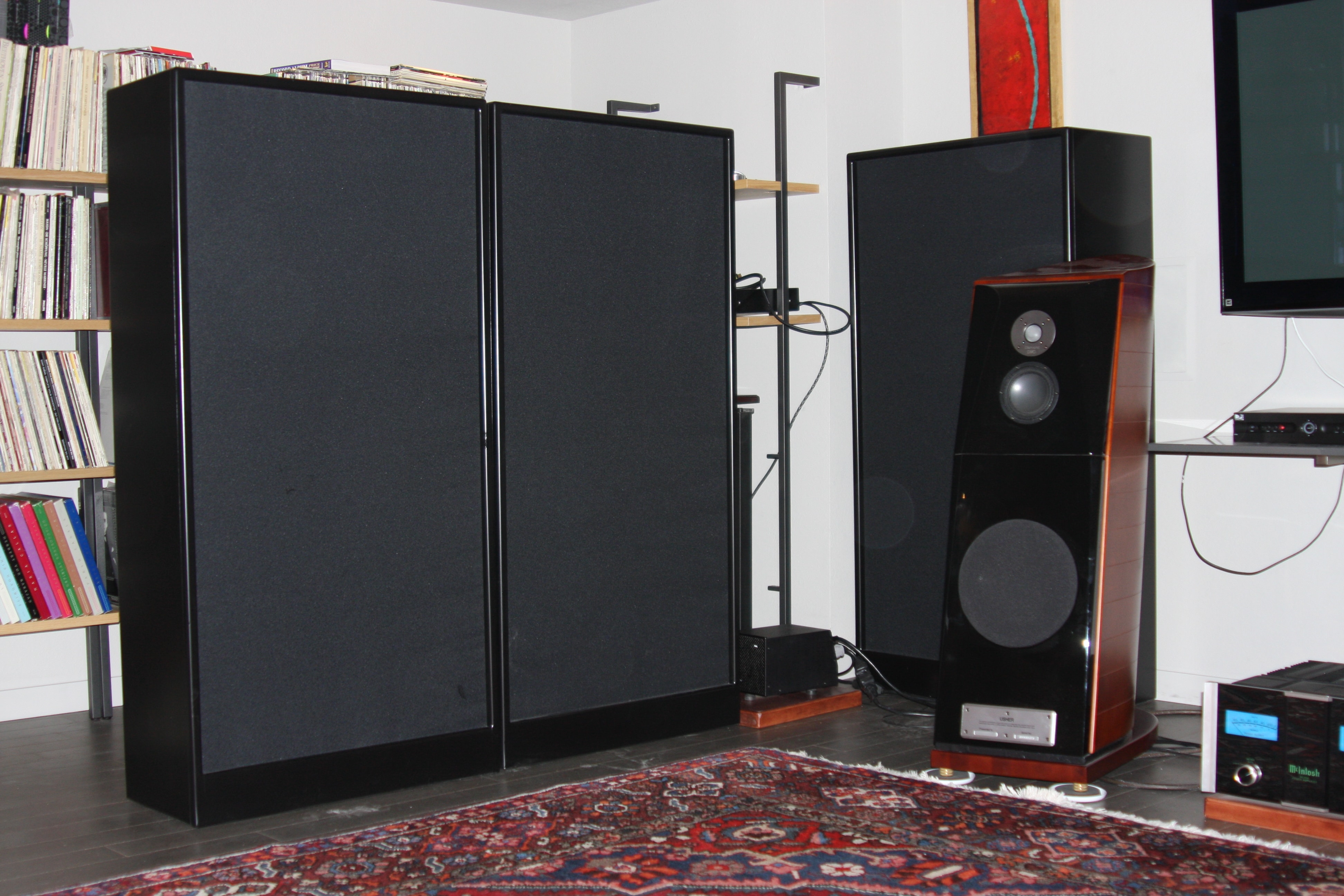
Here are some measurements of panel absorbers:

Such panels can be packed loosely with a porous absorber such as glass fiber to increase the absorption. Again placing the panel at the quarter wavelength or other max pressure spot will be the most effective location. These are often in corners of rooms. Drywall is a good example of a potential panel absorber if designed right. In cases where the depth is not easily apparent, such as the corner absorber the average depth is used.


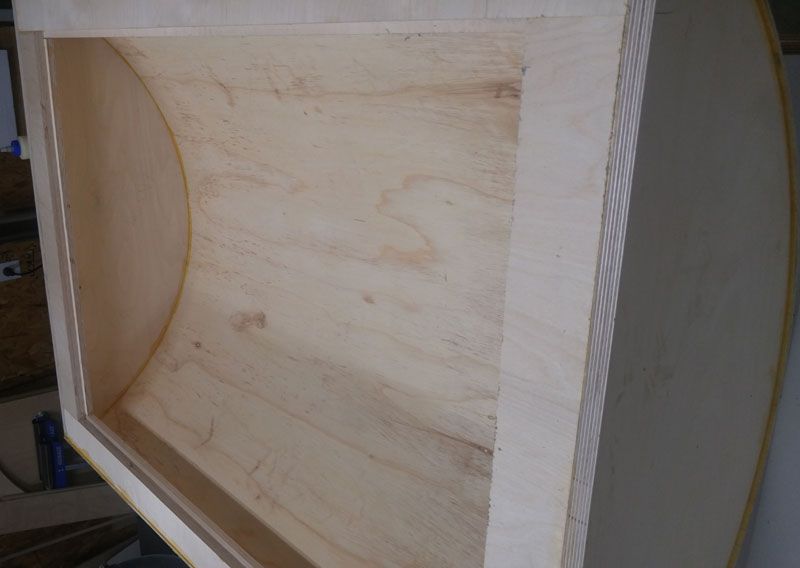
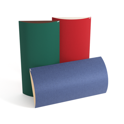
Polycylindrical Absorbers
Polys can diffuse and they can also absorb low end, below 500 Hz. The larger the chord the lower the frequency. Polys behave different depending on if they are empty or filled with absorbent material. This can be handy in some cases.

Here are some measurements of their absorption coefficients and how it can be made more effective by putting absorptive material inside:


This effect occurs at odd multiples of the quarter-wavelength target. Large trap depths are needed for very low frequencies. 40 Hz is 7ft! Hence why false ceilings, floors and the like are implemented.
Constructing Polys
Masonite is a common membrane used. Bulkheads should be randomized to get different natural frequencies. We want these air tight, when sealing them measures need to be taken to ensure they won’t rattle!

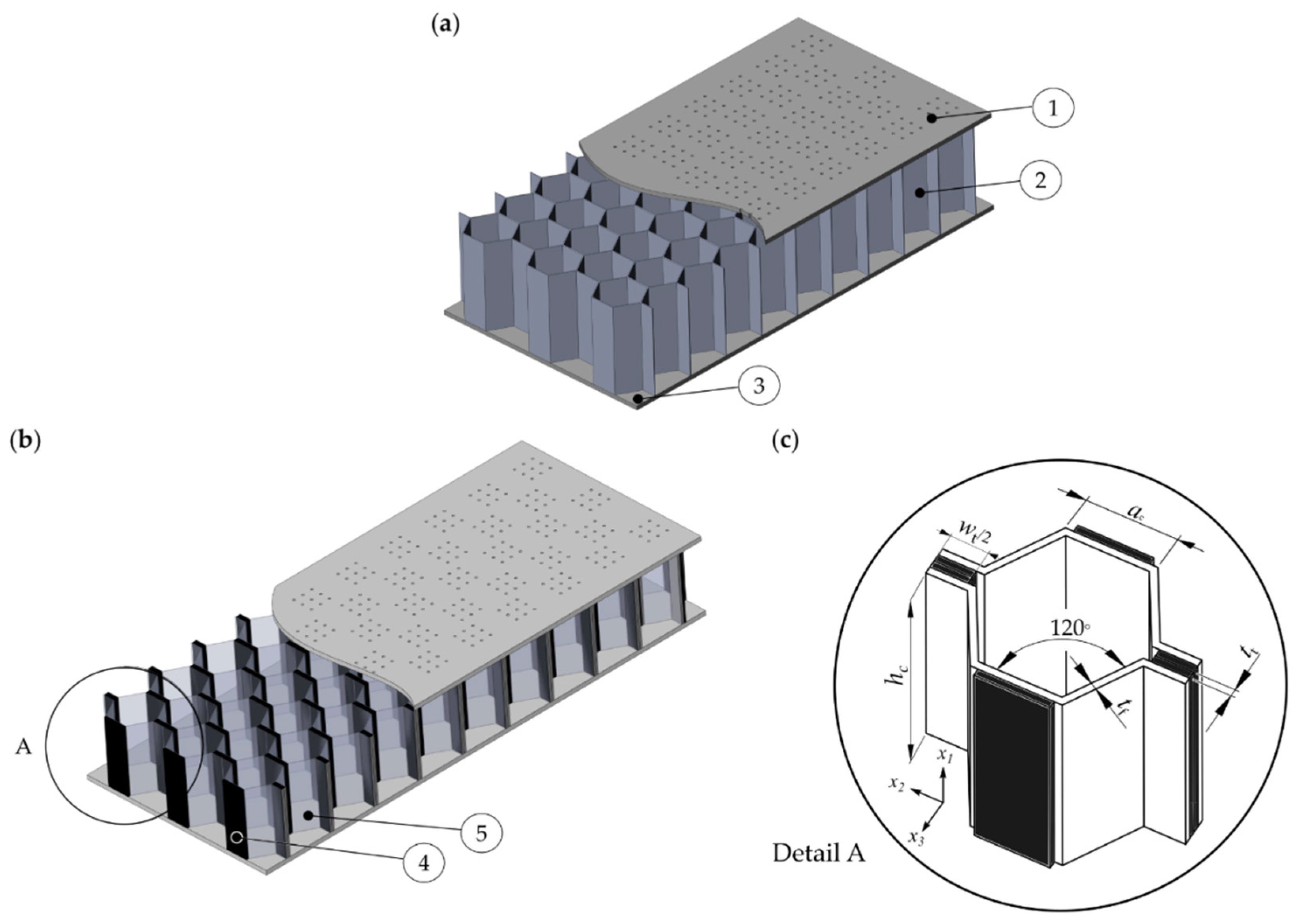
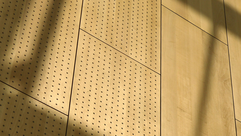
Perforated Panel Absorbers
Plywood, hardboard, aluminum, steel, or other hard surface spaced from the wall will act as a resonant sound absorber. Each hole in the material will act as a neck to a helmholtz resonator, forming what amounts to a coupled helmholtz resonator. Sound hitting the front of such a device will cause all the necks to be in phase, which will be the maximum absorption case and will decrease with non-incident waves. Shaping the cavities can minimize this loss.


For circular holes we can use the following:


As usual you can add porous material to make it more absorptive. It is popular to put a perforated panel a regular porous set up to have it pull double duty.
Perforated Panels with Absorptive in them


Design Table
| Depth of Airspace | Hole Diameter | Panel Thickness | % Perforation | Hole Spacing | Frequency of Resonance |
|---|---|---|---|---|---|
| 3 5/8 | 1/8 | 1/8 | 0.25% | 2.22 | 110 Hz |
| 0.5% | 1.57 | 157 Hz | |||
| 0.75% | 1.28 | 192 Hz | |||
| 1.00% | 1.11 | 221 Hz | |||
| 1.25% | .991 | 248 Hz | |||
| 1.50% | .905 | 271 Hz | |||
| 2.00% | .783 | 313 Hz | |||
| 3.00% | .640 | 384 Hz | |||
| 3 5/8 | 1/8 | 1/4 | 0.25% | 2.22 | 89 Hz |
| 0.5% | 1.57 | 126 Hz | |||
| 0.75% | 1.28 | 154 Hz | |||
| 1.00% | 1.11 | 178 Hz | |||
| 1.25% | .991 | 199 Hz | |||
| 1.50% | .905 | 217 Hz | |||
| 2.00% | .783 | 251 Hz | |||
| 3.00% | .640 | 308 Hz | |||
| 3 5/8 | 1/4 | 1/4 | 0.25% | 4.43 | 89 Hz |
| 0.5% | 3.13 | 126 Hz | |||
| 0.75% | 2.56 | 154 Hz | |||
| 1.00% | 2.22 | 178 Hz | |||
| 1.25% | 1.98 | 199 Hz | |||
| 1.50% | 1.81 | 217 Hz | |||
| 2.00% | 1.57 | 251 Hz | |||
| 3.00% | 1.28 | 308 Hz | |||
| 5 5/8 | 1/8 | 1/8 | 0.25% | 2.22 | 89 Hz |
| 0.5% | 1.57 | 126 Hz | |||
| 0.75% | 1.28 | 154 Hz | |||
| 1.00% | 1.11 | 178 Hz | |||
| 1.25% | .991 | 199 Hz | |||
| 1.50% | .905 | 218 Hz | |||
| 2.00% | .783 | 251 Hz | |||
| 3.00% | .640 | 308 Hz | |||
| 5 5/8 | 1/8 | 1/4 | 0.25% | 2.22 | 74 Hz |
| 0.5% | 1.57 | 105 Hz | |||
| 0.75% | 1.28 | 128 Hz | |||
| 1.00% | 1.11 | 148 Hz | |||
| 1.25% | .991 | 165 Hz | |||
| 1.50% | .905 | 181 Hz | |||
| 2.00% | .783 | 209 Hz | |||
| 3.00% | .640 | 256 Hz | |||
| 5 5/8 | 1/4 | 1/4 | 0.25% | 4.43 | 63 Hz |
| 0.5% | 3.13 | 89 Hz | |||
| 0.75% | 2.56 | 109 Hz | |||
| 1.00% | 2.22 | 126 Hz | |||
| 1.25% | 1.98 | 141 Hz | |||
| 1.50% | 1.81 | 154 Hz | |||
| 2.00% | 1.57 | 178 Hz | |||
| 3.00% | 1.28 | 218 Hz |
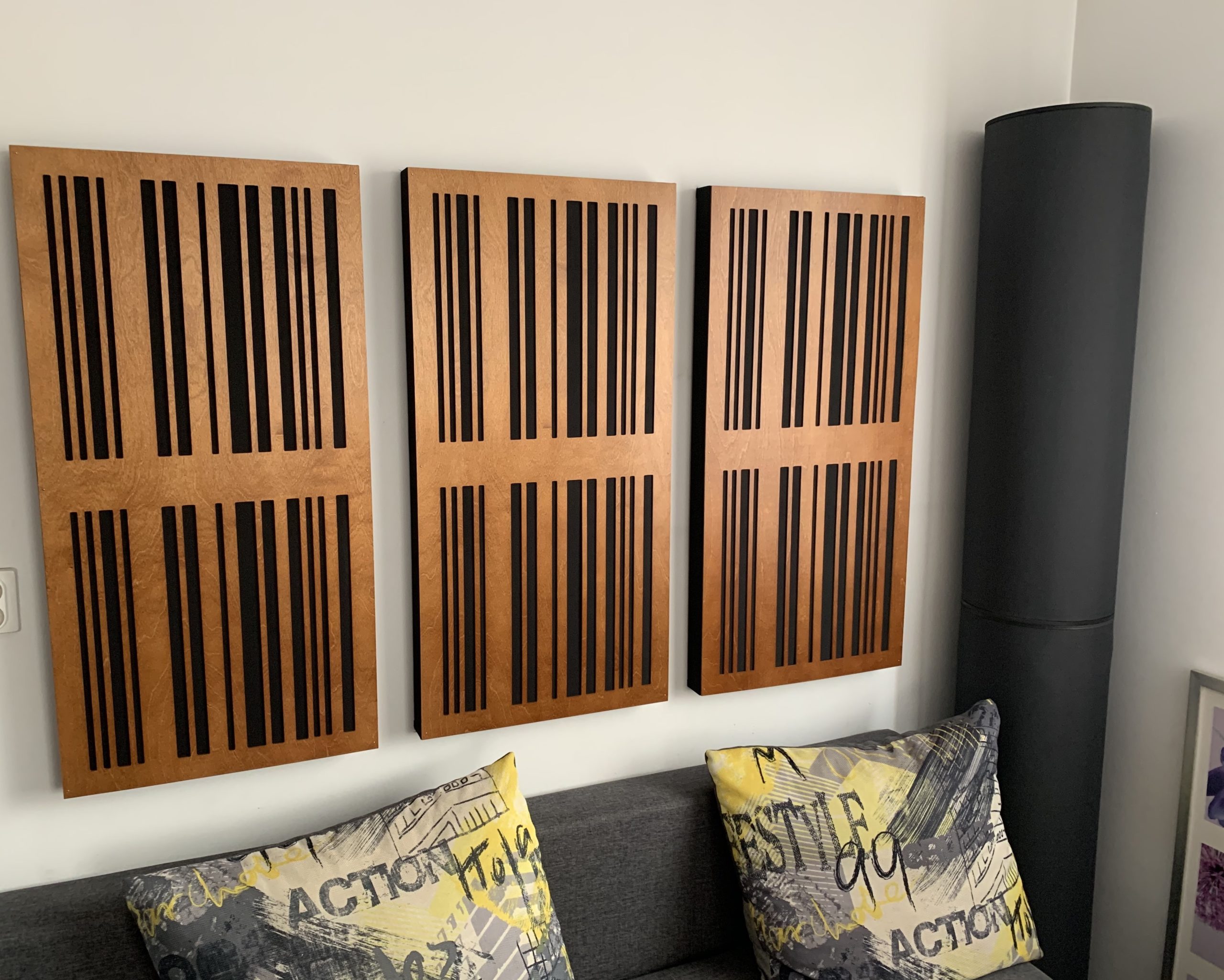
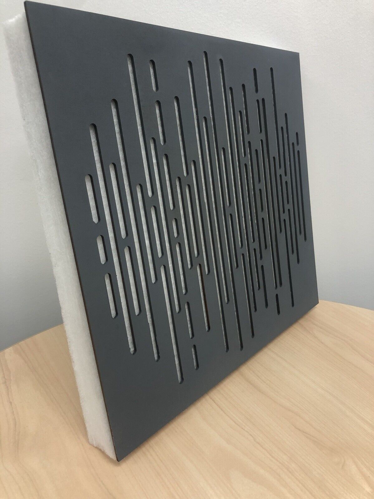
Slat Absorbers
A resonance absorber that uses spaced slats that are closely spaced over an air cavity. The mass of air between slats acts as a spring to form a sort of stacked Helmholtz resonator. Again insulation can be added to broaden the absorption a bit. Narrower slots and deeper cavity = lower frequency of max absorption.
Great paper on slat absorbers: paper.
The equation for a slat absorber is:
Design Question
Given a design frequency target of 300 Hz and a slat thickness of ⅛’’, and a perforation percentage of 3% what should the depth of airspace be?
Given the target absorption frequency is about 150 Hz, using the table what is are suitable specifications for the build? (Hint: Use table 12-3)
Placement of Absorbers
Untreated walls, especially parallel ones, should never face each other. (Standing wave issues)
When using multiple types of absorbers place in patches on all surfaces rather than in one chunk.
Small rectangular rooms will benefit most from absorption in corners and along edges of surfaces.
Apply absorption at the height of the anticipated recording. For example, for speech place absorbers at head height. This can greatly increase the effectiveness of an absorber since it will be a place of earlier reflections.
Close gaps that lead to other spaces. Sound under doors for example can be problematic and solved by simply plugging the gap.
Here are several before and after videos to show acoustic treatment in action!
Adjustable Acoustics
Many rooms require variable acoustics to meet the needs of what the room will be used for. Some studios opt to have entire rooms that are treated separately while others choose variable acoustic options that can be adjusted to change the rooms sonic signature.
Draperies
Drapes, carpets, etc…. Can be drawn out in front of reflective surfaces to deaden a room. Can be very effective at reducing reverb time. Placing at the right distance from the wall helps with low end.
Adjustable Panels
Panels that can be easily added to a wall or removed. There are swinging variants that have diffusion on one side, but these systems can stuffer from leakage to the coupling unit making them lose of their effectiveness as a resonator.


Portable Units
Go betweens or GOBOS are popular for being able to be moved with ease to change acoustic conditions near a microphone. Tube traps are often moveable as well so more the room can be freed up when required.
Survey of Acoustics
Finally to wrap up is a good lecture that covers many of the ideas we talked about here:
To support this series please consider donating via
paypalor joining the
patreon.